傾き補正#
文書のスキャン時に少し傾けてスキャンしてしまった画像があるとする。
画像の分析の前処理として、画像の傾きを水平に直してから処理したい…という状況を想定する
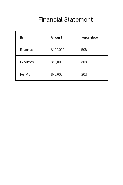
サンプル画像#
ライブラリを使う場合#
import numpy as np
from skimage import io
from skimage.color import rgb2gray
from skimage.transform import rotate
from deskew import determine_skew
import matplotlib.pyplot as plt
grayscale = rgb2gray(image)
angle = determine_skew(grayscale)
print(f"{angle=:.3}")
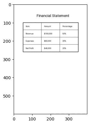
rotated = rotate(image, angle, resize=False, cval=1)
plt.imshow(rotated)
angle=-2.0
<matplotlib.image.AxesImage at 0x7fb830449f90>
表など、まっすぐな直線の要素がある場合#
スキャンした画像が会計の資料などで表が中心の画像だと、表の直線を検知して傾きを計算するのがよさそう
手順:
線の検出
例:Canny法でエッジを推定→ハフ変換で表の直線を推定
例:FastLineDetection
直線の角度を計算
補正すべき角度を計算
回転して補正
Canny法によるEdge Detection#
ハフ変換#
回転#
OpenCV: Affine Transformations
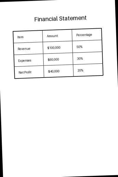
傾かせる
import matplotlib.pyplot as plt

def get_contour(image):
    # グレースケール画像の取得
    gray = cv2.cvtColor(image, cv2.COLOR_BGR2GRAY)

    # 二値化
    _, binary = cv2.threshold(gray, 128, 255, cv2.THRESH_BINARY_INV)

    # モルフォロジー変換:膨張と収縮を繰り返して線を抽出
    kernel_length = max(1, image.shape[1] // 80)  # カーネルのサイズを画像の幅に基づいて決定
    kernel = cv2.getStructuringElement(cv2.MORPH_RECT, (10, 1))
    morph = cv2.morphologyEx(binary, cv2.MORPH_CLOSE, kernel, iterations=2)

    # 輪郭を取得
    contours, _ = cv2.findContours(morph, cv2.RETR_EXTERNAL, cv2.CHAIN_APPROX_SIMPLE)
    contour_img = np.zeros_like(gray)
    # 輪郭を描画
    cv2.drawContours(contour_img, contours, -1, (255, 255, 255), 2)
    return contour_img


# 前処理:表の輪郭線を取り出す
image = get_contour(image)

plt.imshow(image, cmap="gray")
plt.show()

1. ハフ変換による線検出#
Canny法によるエッジ検出#
今回の表については不要かも…?
import cv2
import matplotlib.pyplot as plt

# グレースケールに変換
if len(image.shape) == 3:
    image = cv2.cvtColor(image, cv2.COLOR_BGR2GRAY)

# Cannyエッジ検出を適用
edges = cv2.Canny(image, threshold1=100, threshold2=200)
image = cv2.cvtColor(image, cv2.COLOR_BGR2RGB)

# 結果を表示
plt.figure(figsize=(8, 6))
plt.subplot(1, 2, 1)
plt.imshow(image)
plt.title('Original Image')
plt.subplot(1, 2, 2)
plt.imshow(edges, cmap='gray')
plt.title('Edge Image')
plt.show()

ハフ変換#
HoughLinesとHoughLinesPの違い:
HoughLinesはすべての点の線を取る
HoughLinesPは確率的で、ランダムサンプリングした点だけ計算するので効率がいい
# ハフ変換で直線を検出
lines = cv2.HoughLinesP(edges, rho=1, theta=np.pi/360, threshold=80, minLineLength=10, maxLineGap=5)

# 検出した直線を元の画像に描画
image_for_plot = image.copy()
for line in lines:
    x1, y1, x2, y2 = line[0]
    cv2.line(image_for_plot, (x1, y1), (x2, y2), (0, 255, 0), 2)

# 結果を表示
plt.figure(figsize=(8, 6))
plt.imshow(image_for_plot)
plt.title('Hough Lines')
plt.show()

角度の算出#
def calc_angle(x1, y1, x2, y2):
    """線の傾きの角度を計算する"""
    # 三角形の横xと縦yを取得
    point1 = np.array([x1, y1])
    point2 = np.array([x2, y2])
    x = point2 - point1
    y = np.array([1, 0])
    # cos θ
    cos_theta = x @ y / np.linalg.norm(x) * np.linalg.norm(y)
    # cos^{-1}でθ(ラジアン)を取得
    radian = np.arccos(cos_theta)
    # radian to degree
    degree = radian * (180 / np.pi)
    return degree
# 複数の線の角度を集計
angles = []
for line in lines:
    x1, y1, x2, y2 = line[0]
    angle = calc_angle(x1, y1, x2, y2)
    angles.append(angle)
angles = np.array(angles)

# 縦線は文字の角度を拾っている物が多いので水平に近い線だけをとる
angles = angles[angles < 45]
# 平均をとる
angle = np.mean(angles)
angle
0.9514779758679796
回転#
getRotationMatrix2D
OpenCV: Geometric Image Transformations
affine matrix
\[\begin{split}
\begin{bmatrix}
\alpha & \beta & (1- \alpha ) \cdot \texttt{center.x} - \beta \cdot \texttt{center.y} \\
- \beta & \alpha & \beta \cdot \texttt{center.x} + (1- \alpha ) \cdot \texttt{center.y}
\end{bmatrix}
\end{split}\]
\[\begin{split}
\begin{array}{l}
\alpha = \texttt{scale} \cdot \cos \texttt{angle},\\
\beta = \texttt{scale} \cdot \sin \texttt{angle}
\end{array}
\end{split}\]
を取得する
# 回転の中心を画像の中心に設定
(h, w) = image.shape[:2]
center = (w // 2, h // 2)

scale = 1.0  # スケールは変更しない
rotation_matrix = cv2.getRotationMatrix2D(center, -angle, scale)

# アフィン変換を適用して画像を回転
image = cv2.warpAffine(image, rotation_matrix, (w, h))

# 結果を表示
plt.figure(figsize=(8, 6))
plt.imshow(image)
plt.grid(True)
plt.show()

2. FastLineDetectorによる線検出#
pylsdパッケージのLSDを使ったほうがもっといいかも?
# サンプルデータの生成
image = create_image()
image = rotate_image(image)
image = get_contour(image)
length_threshold = 10
distance_threshold = 1.41421356
canny_th1 = 50
canny_th2 = 50
canny_aperture_size = 3
do_merge = False

fld = cv2.ximgproc.createFastLineDetector(
    length_threshold,
    distance_threshold,
    canny_th1,
    canny_th2,
    canny_aperture_size,
    do_merge
)

lines_raw = fld.detect(image)
# 形状を整える
lines = [line[0] for line in lines_raw]

# # drawSegmentsで描く場合
# img_lines = fld.drawSegments(image, lines)
# plt.imshow(img_lines)

# cv2.lineで描く場合
print(f"{len(lines)} lines are detected")
out = image.copy()
for line in lines:
    x1, y1, x2, y2 = map(int, line)
    cv2.line(out, (x1, y1), (x2, y2), (0, 255, 0), 2)

plt.imshow(out)
32 lines are detected
<matplotlib.image.AxesImage at 0x7fb829d819c0>

角度の算出#
# 複数の線の角度を集計
angles = []
for line in lines:
    x1, y1, x2, y2 = map(int, line)
    angle = calc_angle(x1, y1, x2, y2)
    angles.append(angle)
angles = np.array(angles)

# 縦線は文字の角度を拾っている物が多いので水平に近い線だけをとる
angles = angles[angles < 45]
# 平均をとる
angle = np.mean(angles)
angle
1.6194360861896437
回転#
getRotationMatrix2D
OpenCV: Geometric Image Transformations
affine matrix
\[\begin{split}
\begin{bmatrix}
\alpha & \beta & (1- \alpha ) \cdot \texttt{center.x} - \beta \cdot \texttt{center.y} \\
- \beta & \alpha & \beta \cdot \texttt{center.x} + (1- \alpha ) \cdot \texttt{center.y}
\end{bmatrix}
\end{split}\]
\[\begin{split}
\begin{array}{l}
\alpha = \texttt{scale} \cdot \cos \texttt{angle},\\
\beta = \texttt{scale} \cdot \sin \texttt{angle}
\end{array}
\end{split}\]
を取得する
# 回転の中心を画像の中心に設定
(h, w) = image.shape[:2]
center = (w // 2, h // 2)

scale = 1.0  # スケールは変更しない
rotation_matrix = cv2.getRotationMatrix2D(center, -angle, scale)

# アフィン変換を適用して画像を回転
image = cv2.warpAffine(image, rotation_matrix, (w, h))

# 結果を表示
plt.figure(figsize=(8, 6))
plt.imshow(image, cmap='gray')
plt.grid(True)
plt.show()
